5703 County Road 6220 Bldg 12 Lubbock, TX 79415
A part example from start to finish
We start with a ordinary CAD drawing done with TurboCAD
We start with a ordinary CAD drawing done with TurboCAD

The part is simple, but challenging with an island in a deep cavity to navigate around and a large radius that needs to be hand finessed on both sides to maintain the wall thickness.
Cut some rough stock from raw material
We start with a ordinary CAD drawing done with TurboCAD

The raw material
Square up the rough stock

A solid slab of aluminum. Next we machine all 6 sides to square-it-up and establish the overall outside dimensions.
Square up the rough stock
Square up the rough stock
Square up the rough stock

Machine the rough stock on all sides into a configuration that's nice and square.
Not shown is how the part geometry is oriented to the machine. All we do is edge-find the corner that is the origin and set the Display XY ZERO and DRO XY ZERO
The work station
Square up the rough stock
Let the chips fly !

Machining done on an ordinary "Bridgeport" style mill. Note the "Fish Tank" enclosure to keep the machinist dry, preserve the coolant and for chip control. Without it, all the chips and coolant would be all over the floor, and me. The Cartesian Display with the CAD geometry is below the regular DRO.
Let the chips fly !
Square up the rough stock
Let the chips fly !

We don't need no stink'n scribe lines. Note that the machinist can run completely blind, He is looking at the display, his face is not down in the cutting action trying to navigate the tool the old way. Here the part is buried in chips and you can't see a thing, NO PROBLEM because the Cartesian Display gives us Virtual Scribe Lines.
Rough machine in several depth passes, finish at full depth
Rough machining
Finish machining (switch to 4-flute endmill)
Roughing complete

The cavity is 1-3/4" deep ! Easily machined while navigating precisely around the island.
Roughing complete
Finish machining (switch to 4-flute endmill)
Roughing complete
The cavity was machined with 17 0.100" passes to get to the final depth. This operation left 0.020" left on all surfaces.
Finish machining (switch to 4-flute endmill)
Finish machining (switch to 4-flute endmill)
Finish machining was done at full depth of cut to remove the 0.020" left during roughing and to get the final dimensions. Final dimensions achieved using Radar Mode.
Finish machining

I did not have a high quality carbide endmill but it still looks pretty good except for the line in the finish due to a defect in the tool.
Done !
All that's left is to drill the holes, but that's the easy part.
The Cartesian Display Prototype

The Prototype shown mounted under the standard DRO.
The finished piece
Finished piece, washed, no hand finishing
Finished piece, washed, no hand finishing
Finished piece, washed, no hand finishing
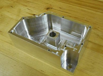
This view shows the inside, the hand-cut radius looks decent even with no secondary operations such as sanding or polishing. All dimensions came out +-0.002 without trying, no adjustments and without knowing ANY of the dimensions at the time of machining. Using Radar Mode to place the tool exactly on each surface.
Finished piece, washed, no hand finishing
Finished piece, washed, no hand finishing
Finished piece, washed, no hand finishing
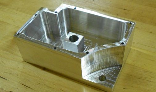
The endmill used was of poor quality, note the line left in the finish. This view shows the hand cut large radius. It took several minutes to cut, but even with no hand-finishing, the finish looks quite acceptable.